HK1 Stirling Engine Plans
Important
This is page one of the plans. Bookmark it. They may be printed or saved for later viewing.
The URL of this page (for updates) is //comptune.com/tincan/hk1/plans1.htm
10/26/2012: The plans ebook is now free! Donations are still welcome, of course :).
11/03/2002: The Stirling engine plans are also available in .pdf format (Thanks, Abe F.)
10/7/2002: These plans are now available in word format for easy printing on most printers. To print the booklet on a laser printer (face down) set it to print 2 pages per sheet. Print pages 12,1,10,3,8,5 then put the stack back in and print pages 6,7,4,9,2,11. Fold, staple twice and trim the edges to make a nice 4 x 5 booklet just like the kind we mail out.
For questions or suggestions, please email me.
--Henry Kroll
Click the link below to get started. Happy building!
Home
Animated Illustration
Back to Stirling Info Page
Copyright © 2012 Henry Kroll, All rights reserved.
Introduction
The Stirling Engine was patented in 1816 by a clergyman, Robert Stirling. That's why it's not spelled sterling as in sterling silver... At the time this engine was invented, steam power was commonplace. Possibly some attendees of Stirling's congregation were affected by accidents and boiler explosions connected with this form of power. Air engines offered a safer and cheaper alternative. What Robert added to the design was a regenerator which acts as a heat exchanger and heat recycling device, increasing the efficiency dramatically.
Benefits
Almost anyone can build a Stirling engine: Most designs don't require complex parts such as spark plugs, injectors, valves or camshafts. There are even designs with only one or two moving parts.
Stirling engines don't use much fuel: Up to the 50% theoretical maximum thermodynamic efficiency has been achieved with modern designs.
Quiet operation: Stirling engines burn their fuel externally and continuously rather than in a series of explosions.
Versatility: Stirling engines can run on almost any type of fuel, including solar, chemical geothermal and even nuclear. All that is needed is a natural or artificially created heat difference.
Limitations
Low power output: Power is dependant on the thermal expansion coefficient, overall thermal transfer efficiency
(Rth=°C-in²/W) of the engine, friction and volume of the working fluid (can + cylinder & displacer). The unit described in these plans cannot produce much power due to its low pressure operation and small size. Modern designs overcome these limitations by pressurization of the working fluid and the use of other working fluids with higher expansion coefficients and thermal transfer, such as helium.
Slow Starting: It can take a minute or more for a Stirling engine to get up to speed. It would not make a very good getaway car!
Presentation Ideas
There are many handy graphs and equations explaining the stirling cycle on the internet. Just do a search for "e;stirling cycle".nbsp; Energy and efficiency graphs comparing stirling with conventional 4-stroke engines would make a good science fair presentation. Just make sure and understand the formulae or it will be tough answering questions!
Parts List
| Quan. | Description |
| 1 ft. | 17/32" x 2" brass tube (Must accommodate piston below snugly but without drag) |
| 1 | ½" x 2" long aluminum, steel or graphite rod. (get one that is a good fit with the above tube) |
| 3 | 1/16" square brass tubing (tubing comes in 1 ft. lengths) |
| 1 | 1/16" brass rod |
| 1 | 3/32" copper tube |
| 2 | cans 4" diameter soup or stew tins (tin plated steel) |
| 1 | plastic tubing that fits snugly over 3/32" copper tube (1 foot length is ok) |
| 1 | 1/4" x 4" x 4" minimum scrap of ceiling tile, stiff fiberglass insulation or basically anything porous, light weight and fire resistant that can easily be cut and formed into a displacer. |
| 1 | fuel: candle, solar dish, kitchen or camp stove, etc for heat source and possibly some water, snow or ice cubes for cooling |
Tools
Soldering Iron and solder (40w + recommended)
ball bearing compass or drafting compass/dividers
sand paper or sander
high temp silicone, JB Weld, or Devcon™ metal
patch & fill
razor knife and hacksaw or Dremel™ cutter
pliers and wire cutters, spray lube
tubing cutter, tin snips, can opener
Get metal rods and tools from local hobby shop. I went to Anchorage House of Hobbies, 2812 Spenard Rd., Anchorage, AK 99503. Hardware stores also carry metal rods and tubes. They may also be ordered from K&S Metal Center, 6917 W 59th St., Chicago, IL 60638. They also have a website: //www.ksmetals.com The tin can can be bought at a local grocery. They usually contain edible food products. Mine contained yummy beef stew. The ones with the shiny tin tops (not the dull enameled ones) are easier to solder since they don't need to be sanded first. This document assumes knowledge of how to solder.
There is also a solder-it kit available at
//www.solder-it.com but I
haven't tried it. If anyone decides to use this kit at their own
risk and tell me how well (or not) it works, I'd be glad to know.
It supposedly allows one to fuse dissimilar metals such as brass to pot
metal and offer 5 to 10 times the strength of conventional solder.
The cost at this writing is $59 for the kit.
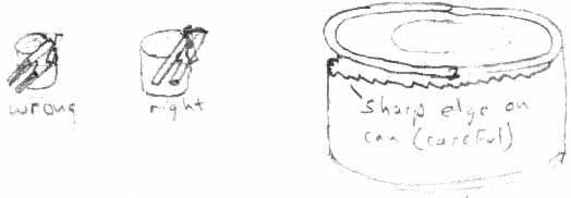
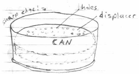
1) Obtain two cans roughly 4" dia. and 1 1/4" tall. Using the can opener, open the cans along the outside of the seam, not the top. This is not the usual way to open a can and may take some getting used to. Save the lids. Be careful as this will leave a razor sharp edge that is very dangerous!
2) Eat the contents in the normal way.
3) Using the tin snips, cut one can down to roughly 1 1/4" tall if it isn't already that height. Taller cans will require longer pistons/rods and more care.
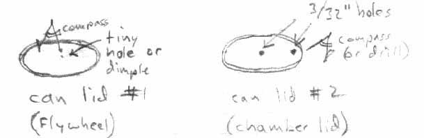
4) Take those lids, and using the compass, find the center point on each. Poke a tiny dimple into the center of both lids with the compass. Poke or drill out a 1/16" hole in one lid and a 3/32" hole in the other. About 1/2" from the edge make yet another 3/32" hole. The tubing should fit snugly into these 3/32" holes for soldering later and the 1/16" rod should also fit snugly in the 1/16" hole in the first lid.
5) Using the razor knife or tubing cutter, cut off four 1/2" lengths of the copper tube. With the razor knife use a rolling motion. The finished cut tubes will be crushed slightly inward, so flare them back out with the compass point. Finish off any rough edges with sander or fine sand paper.
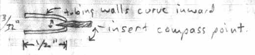
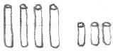
Next, cut and finish three more tubes 1/4" in length. There should now be four1/2" tubes and three 1/4" tubes:
6) Sand around the holes in the can lid and insert two of the 1/2" copper tubes. Solder in place. Be careful not to block the holes! Make sure center tube is perpendicular to the can lid. Alignment is very critical at this stage.
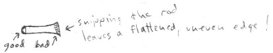
7) Using the wire cutters, cut three 2" pieces of 1/16" brass rod. Don't just snip off with wire cutters, but turn the rod while applying pulses of gentle pressure: The freshly cut rod should be able to slide easily into the above tubes.
8) Make a displacer by cutting the semi-porous fire resistant material in a circle. Make it small enough to fit easily inside the can without touching the sides. It should move freely up and down. Trim off any excess. Find and mark the center and drill a 1/16" hole through it.
9) Efficiency may be improved by drilling several more holes in the displacer. This will allow air to pass through easier and that will also help it to recycle some lost energy.
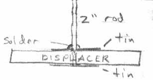
10) poke the 1/16" brass rod through the displacer and glue in place. Make sure the rod is perpendicular to the displacer surface. Very important! For a longer lasting engine, roughen up the brass rod first, but only in the area contacting the displacer. Thin tin 'washers' may be made and placed on either side of the displacer and soldered in place just in case the glue fails. Note: do not leave a big blob of solder like the diagram below. This will get caught in the seal and reduce free movement of the displacer significantly!
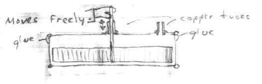
11) Insert the rod and displacer assembly into the top lid made in step #6. Make sure it moves freely. If not, remove burrs from the copper tube with a compass point. Place the lid and displacer onto the can made in step #9 and put a bead of glue around the top of the can. Alternately, solder the entire edge, but this will require lots of sanding. Use high temperature silicone adhesive or Devcon™ Metal Patch & Fill. I used epoxy but was disappointed when it melted when the engine overheated one day. Again, make sure displacer moves freely up and down before glue dries. When the glue does set, be sure to check for leaks! How? Plug the hose into the other open tube and blow into it while applying some soap with a sponge to the freshly glued edge.
12) Measure the exact distance the displacer can move up and down. This is the stroke.
13) Take another rod and bend the crank. Bend it slightly less than 1/2 of the stroke to account for possible error. This is important as too much stroke will cause the displacer to hit the top and bottom of the can, adding to friction and wear.
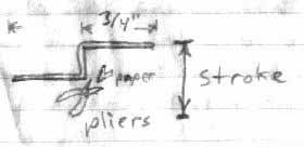
Use notebook or graph paper to check crank: Make sure it is parallel!
Note: Use folded paper in the jaws of the pliers so as not to score the bearing surfaces. Fold several layers of paper... Cut and re-solder instead of bending if bending is too difficult.
14) Slide the crank into one of the 1/2" long copper tubes cut in step #5. Solder flywheel to end of crank. Use extreme care so as not to accidentally solder the bearing to the crank in the process!
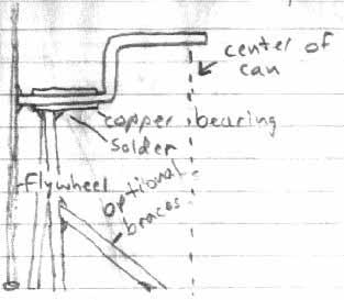
15) Cut two 4" lengths of square tubing and use left over pieces for
braces. These will be the two upright braces holding the flywheel and
crank up. See diagram below for general layout. Solder braces to crank
and to can, making sure everything lines up properly and is square /
plumb with can top. Center as best as possible. It doesn't have to be exact,
but an off-center wobble may make the engine function poorly. At least solder
joints are easy to heat and re-adjust. Be
careful not to get burned!

16) Turn crank to the down position. Slip on one of the 1/4" copper tubes. Solder another 1/4" tube to the displacer rod and then connect the two bearings with square tubing. This links the crank with the displacer. Adjust until the crank turns freely, moving displacer up and down.
17) Slowly turn crank and adjust linkage for minimum friction. Too
long a linkage and the displacer will hit the bottom of the can. Too
short and displacer will hit against the top of the can. Add a counterweight to the flywheel
by applying a large blob of solder
to the rim opposite the crank. The linkage can be removed
for demonstration and shipment, but it should stay in place as the crank rotates.
18) Cut the 17/32" brass tubing about as long as the can is tall (1-1/4"). This will be the cylinder wall. Tubing cutters are ok but they will crimp the tubing slightly. Solder some tin to the cut end. No leaks!
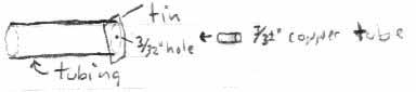
19) Poke a 3/32" hole (or drill) in the tin plate at the end of the "cylinder". Solder a 1/2" length of 3/32" copper tube in the hole. Again, sand the hole first so the solder will stick and check for leaks.
20) Cut the 1/2" aluminum rod to the same length as the cylinder tube. This will be the "piston". Using the hacksaw, cut a slot 1/4" deep in the rough, freshly cut end of the cylinder:
Carefully sand the rough edges. Do not score the sides of the cylinder too much or there will be added friction.
21) Drill a 1/16" hole straight through (across) the notch in the cylinder to make a hole for the hinge pin:
22) Cut a piece of tin and solder a 2" long 1/16" brass rod to it. Put a 1/16" hole in the end. This is the piston rod:
23) Assemble the rod and piston and insert a 9/16" length of brass rod through the holes in the piston. This is the hinge pin. Solder won't stick to the aluminum piston, but blobs of solder on the ends of the rod will keep it from sliding out. There might be better ways to do this but this worked well.
24) Insert the piston into the cylinder. It should move freely in and out. If not, then polish the affected area until smooth. Lubricate with a spray lubricant, light oil or graphite.
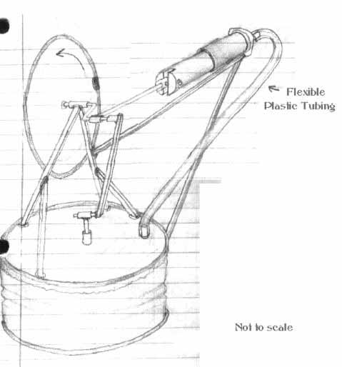
25) Using square tubing and solder, mount piston to the side of the engine can in-line with the horizontal center of crank. Things should be starting to look like the picture:

Click image to enlarge
26) Remove the displacer linkage and slip a 1/4" length of 3/32" copper tube over the crank. This is the rod bearing.
27) Calculate rod lengths by turning the crank to the maximum right (horizontal position). Move or push the piston in until it is near the bottom of its free travel into the cylinder. Cut the piston rod to this length and solder it to the rod bearing. Refer to the picture on the last page to see that it has been done correctly. Now there should be free piston travel throughout the entire turn of the crank. If not, adjust linkages until it runs as smoothly and freely as possible.
28) Replace displacer linkage and connect plastic tubing from the air chamber to the piston. It should slip snugly over the copper tubing with no leaks.
29. Turn crank and check for easy piston and displacer movement. Engine is now ready to run. Lubricate all moving parts. Do not use heavy oil or grease. WD-40™ works, but it eventually turns to grease, which will hamper performance.
Apply heat to the bottom. An electric range works very well. So does a gas stove on low, a candle, or even a cigarette lighter or focused sunlight. A small ice cube on top helps to keep it cool. The additional cooling will make it run faster. Apply low heat for a minute, then gently turn the crank counter-clockwise to start engine. Remove from heat to shut off. CAUTION! The engine can get quite warm and it's possible to burn fingers. Wear oven mitts or heavy gloves. Another modification is to take some scrap tin and make a handle to hold the engine but be sure to round the edges so they're not sharp. Don't let the engine get too hot or it might melt the solder. It should be able to run at temperatures well below that point!
Additional Notes: The first prototype was very well machined to exact tolerances. It did not work. A tiny bit of air must be able to leak through the displacer rod seal. If no air can escape from the engine then the piston will seize in the out position during warm-up due to expanding air inside the can. Built with these handy materials the amount of leakage should be ideal (depending on how much lubrication is used. Too much lubrication will plug the seals entirely and make for hard starting.) Loose fitting parts also guarantee less friction. Engine must be able to spin freely or it will have trouble working.
Advanced Projects: Connect another piston to the other side. Presto, a heat powered air pump. With a slight modification, the cylinder can be made to flip over to the other side, making the engine run in reverse. Extend the shaft and attach fans or pulleys to it and make it do work. How about a candle powered paddlewheel boat? Extend the crank and add more cans and pistons. A two cylinder engine should be almost self-starting! See if different crankshafts make it run smoother. Try making a solar collector...
Have fun!