JavaScript animation © Hank Kroll
Here is an working illustration of the model HK 1, a displacer type stirling engine in operation. The green pad moving up and down is the displacer. It displaces the air alternately to the hot and cold side of the engine. It is made of porous material so as it moves back and forth, it retains some of the heat so it can be used again in the next cycle. The displacer is the most important advancement in heat engines, improving their efficiency by recycling the heat (instead of throwing it away like car engines do). I wonder what the effect on global warming would be if we all used stirling power...
When the air is displaced back and forth it becomes alternately hot and then cold and thus expands and contracts accordingly, moving the piston. This principle is known as Charles' Law. Hot air expands and cold air contracts. For illustration, try blowing up a balloon and putting it in the freezer for a few minutes. Take it out and watch it expand as it warms up to room temperature again... It's what powers the weather. Inside the engine there is only air at atmospheric pressure. There is no steam, no exotic gasses or anything else that could explode or otherwise cause harm to persons or the environment.
The orange cones (candle flames) in the above illustration represent the heat source and the ice cubes on top represent the cooling necessary for continued operation. The green pad that moves up and down is the displacer. The piston is mounted horizontally. Notice how the motion of the displacer leads that of the piston by a quarter turn. This is very close to the ideal for this type of engine.
To start the engine, heat is applied to the bottom and cooling is applied to the top surface. The crank is turned slowly counterclockwise until the engine starts.
When looking at the above animation, keep in mind that the air inside the engine is expanding and contracting, pushing and pulling on the piston. All of the work that goes into turning the engine is done by the piston. The displacer is completely passive and is moved up and down by the crank. It only acts to displace air which would ordinarily be in contact with hot and cold surfaces.
Go ahead and stop and start the presentation a few times and try to imagine the various forces at work upon the piston and linkages. The whole concept is so simple it will amaze.
Note also that the displacer is semi-porous and does not touch the sides of the can. Air can flow through it as well as around it. This causes the air to pick up some of the heat left behind from the last cycle and makes the displacer also a regenerator. A good regenerator can increase the overall thermal efficiency of an engine by as much as 50%.
The engine goes through 4 general phases of operation as outlined below:
|
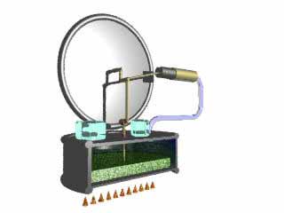
1. Vacuum power stroke. In this frame, the crank and displacer is in its lowest position and the piston is halfway in. The bulk of the air is displaced to the top of the can where it cools. Cooler air takes up less volume so it immediately forms a slight vacuum inside the engine which tends to pull the piston inward |
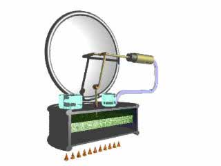 |
2. Heating Cycle: The piston tugs sharply on the piston rod and the crank turns until it is in the rightmost position. Some of this energy is stored in the flywheel, which carries the crank around until the displacer is lifted up. |
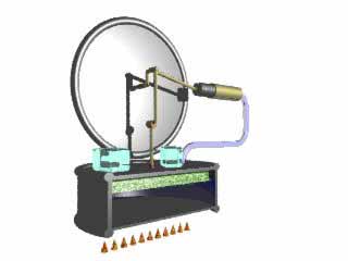 |
3. Pressure power stroke. With the displacer in the up position, the air inside the whole engine experiences rapid heating and builds up pressure forcing the piston out to the left. |
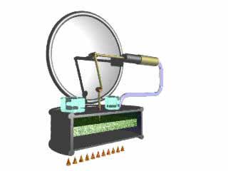 |
4. Cooling Cycle: The crank turns and moves the displacer back down. The air rapidly cools and the cycle begins again. |